 So let's start here. This is the key to understanding how the Haskel works.
This is the spool and sleeve that are used to
direct the drive gas to the appropriate end of the drive cylinder and to vent
the exhaust on to the heat exchanger.
This is what I think is the smart bit.
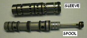
So let's start here. This is the key to understanding how the Haskel works.
This is the spool and sleeve that are used to
direct the drive gas to the appropriate end of the drive cylinder and to vent
the exhaust on to the heat exchanger.
This is what I think is the smart bit.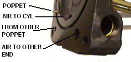 The sleeve mounts in the bottom of the block in the big hole. It is feed with
drive gas into it's centre section, the left hand end is connected via a pipe
to the far end of the drive piston and the right hand end feeds directly to the
near end. As the spool moves back and forth drive gas is directed to alternate
ends and exhaust gas is vented to the hollow body of the spool.
The sleeve mounts in the bottom of the block in the big hole. It is feed with
drive gas into it's centre section, the left hand end is connected via a pipe
to the far end of the drive piston and the right hand end feeds directly to the
near end. As the spool moves back and forth drive gas is directed to alternate
ends and exhaust gas is vented to the hollow body of the spool. This space at the end of the spool is also coupled to a similar poppet at the
other end that vents to the open air removing the pressure so the spool is
no-longer held right and the pressure of the exhaust gas within it drives it
back to the left. There is a slight tweak using the piston on the end of the
sleeve to reduce the overall effect of the exhaust pressure but that enables
Haskel to run without springs except in the valves and without detents. Frankly
I'm impressed. This is probably why my 20 year old pump looks so new inside
once I'd cleaned it up.
This space at the end of the spool is also coupled to a similar poppet at the
other end that vents to the open air removing the pressure so the spool is
no-longer held right and the pressure of the exhaust gas within it drives it
back to the left. There is a slight tweak using the piston on the end of the
sleeve to reduce the overall effect of the exhaust pressure but that enables
Haskel to run without springs except in the valves and without detents. Frankly
I'm impressed. This is probably why my 20 year old pump looks so new inside
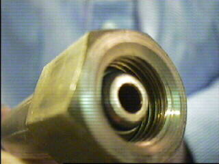
once I'd cleaned it up.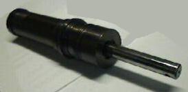 The piston drives the high pressure pump which, as you can imagine when we
discuss 775bar, is this thick walled device. The drive shaft is a close fit in
the 16mm bore but to compress 775bar would take about 1500Kgs of force, a ton
and a half roughly, so it needs to be serious metal.
The piston drives the high pressure pump which, as you can imagine when we
discuss 775bar, is this thick walled device. The drive shaft is a close fit in
the 16mm bore but to compress 775bar would take about 1500Kgs of force, a ton
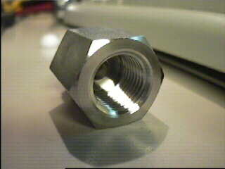
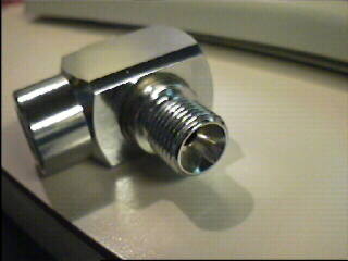
and a half roughly, so it needs to be serious metal.Unfortunately the part I wish to screw into this is shaped as P4 (SAC 1625) and it will not sandwich a washer as it has a cut out for the conical adapters of the hoses as in picture P5.
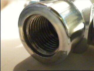
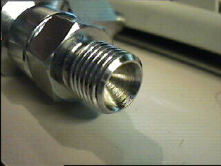
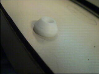
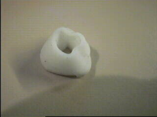
I started by trying to sandwich an O-ring regardless of not having a cut out but that popped out at about 80 bar so, after some experiments I contacted SAP who tried to solve the problem by making the washer shown in P6 with a conical end to go into the screw in and a flat side to mate up against the Swagelok fitting. The part looked right so I assembled it finger tight and put some gas pressure on it. It hissed. I gently tightened the fittings. It hissed less, less, less, more. OH DRAT. Tightening it up and applying pressure had rendered it P7.
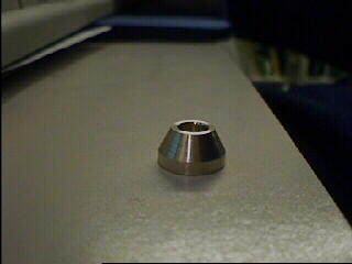
There was a delay but when I discussed it with SAP we came to the conclusion that we needed metal and settled for Brass. They made the part shown in P8 and I sandwiched an O-ring below the flat side and spannered it up. I let the presure on gently - no hiss so I assembled the other side and tested it. Chuff-phut, Chuff-phut we were pumping gas.
We fixed it but it does seem ironic that the biggest problem was nothing to do with pumping reactive gas at high pressure they were just the usual run of the mill problems you get connecting any two dissimilar systems.
The only other snag is that a 770bar pump will destroy a 275bar gauge in moments if you shut the valves in the wrong order. <sigh> Such is life.