Nigel and the Lathe : more of a blog than a review
Installation |
Feed gears |
QCTP |
Slide |
T-slot cover |
Gadgets |
Carriage lock |
Tool height aid |
Power switching |
Tailstock DRO |
Milling |
Press |
Other Tools
Personally I blame my brother.
I have lived happily for 55 years without a metalworking lathe in my toolbox
and suddenly he has got me all started up again.
OK, let's recap some background. Nigel and Robin are a small company. I do the
programming, the physics and the electronic design and he actually turns our
ideas into reality, saleable reality and then he runs manufacturing, sales and
support. ie: I do the fun stuff and he does the hard stuff.
The business has done quite well over the years and Robin recently decided he
needed/deserved some new machine tools because he's been struggled by doing his
prototyping on old stuff for too many years. What he wanted was a big butch
milling machine and a 'proper' lathe.
I forget the details of the conversation at our weekly management meeting, held
over lunch in convenient Carvery in Peacehaven, but I think I was reminiscing
about lathes I have known and loved and he suggested that I might want a lathe
too.
 Now this wasn't such a silly idea. I often need machined components for my part
in a project and feeding the job and any subsequent modifications back onto him
costs time. Also I had learnt all this stuff at school. I was once almost quite
good at it and I joined the after school metalwork club precisely to get more
access to the machine tools than my O-level course required. I still have items
that I made on a school lathe in my toolbox some 55 years later although I
doubt I will ever be called upon to punch a hole for a B9A valve holder in an
Aluminium chassis today. (Hobby electronics was serious stuff back
then.)
Now this wasn't such a silly idea. I often need machined components for my part
in a project and feeding the job and any subsequent modifications back onto him
costs time. Also I had learnt all this stuff at school. I was once almost quite
good at it and I joined the after school metalwork club precisely to get more
access to the machine tools than my O-level course required. I still have items
that I made on a school lathe in my toolbox some 55 years later although I
doubt I will ever be called upon to punch a hole for a B9A valve holder in an
Aluminium chassis today. (Hobby electronics was serious stuff back
then.)
So Google and I started looking at lathes: Hobby lathes aka Mini lathes. They
did look rather fun. So I pitched two I rather fancied to Robin to see what his
opinion of them was.
Well he rather trashed my suggestions. They just failed on so many of his
'obvious' requirements. They were damned for being too small, too light weight
and, frankly, they both would be a disappointment long term as they just
wouldn't have the strength. They were, admittedly, just toy lathes.
<sigh>
I was, perhaps, just a little out of date and needed re-educating. Also, he
pointed out, I just wasn't planning on spending nearly enough to do the job
properly. Sadly nothing beats bulk cast iron when you want rigidity and bulk
iron equals weight equals money.
I'm not going to detail the whole reasoning process that we went through as I
went through the catalogues with him immediately fingering what they did not
say so let's jump straight to the conclusion and this is what we ended up
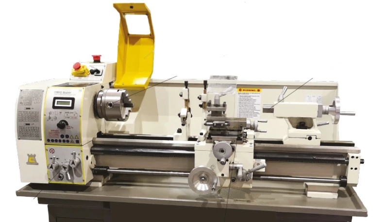
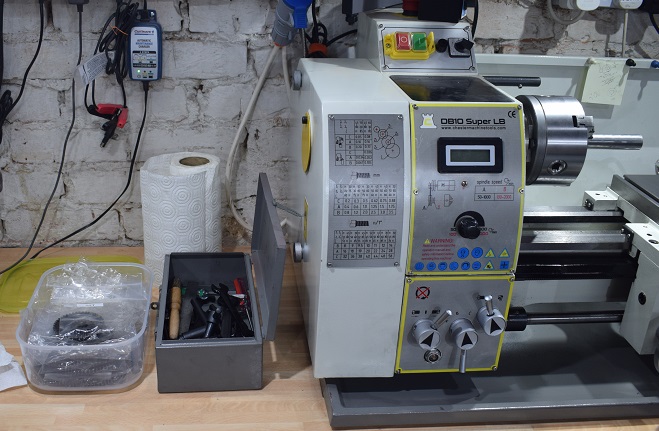
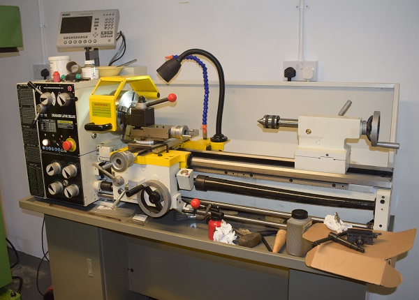
ordering, the Chester DB10 long bed lathe. It has the right basic hardware
and, anyway, because Robin approves of it I'm not going to be embarrassed when
I need to go back to him to ask for further advice. We have put the money into
the basic unit as I can add gadgets later and, now that I have researched
modern lathes a bit, I know of lots of gadgets that I really want to have to
play with.
Well YouTube is full of 'unboxing' videos for virtually every product
imaginable however they mostly seem just to be there to flaunt 'Look, I have a
thing now' and don't actually help other people planning on walking the same
road. Well I'm not going to inflict another one of them on the web. What I felt
was normally lacking in the lathe ones were some hints as to how a 71 year old
kid goes from having boxes being dropped off at his house by a truck to
actually having a working lathe sitting on his bench cutting metal. Remember
this monster, according to the spec sheet, weighs in at 145kgms while I only
weigh 70.
So, even if I do get to flaunt my own 'Look I have a lathe now' web page/video,
at least I can try to earn my fifteen minutes of fame by admitting to the
problems, some self inflicted, that I ran into and then giving examples of how
I overcame them so others can filter out any useful ideas or just laugh at
me.
I started the planning several weeks in advance as we were all on COVID
lockdown at the time. I have a bench standing on big timber legs that it can go
on. That's not the problem. The problem is that a lathe arrives bolted into a
solid packing crate. I can demolish the box around it but I will still need to
pick it up from the base to get at it all round and fit the DRO (Digital
ReadOut) option we have ordered as a bolt-on kit. Then I need to pick it up
again and put it on my bench which will back it up to a wall, align it with the
holes I will have drilled and bolt it down.
So... I have a cunning plan:
I will meet the delivery truck by the roadside with my trolley.
If it has more than one box anything that is not core lathe that I can man
handle through the front door can sit in the hall for later investigation.
I then trundle it round the back lane on the trolley, up the garden path and
park it on the patio while I move the motorbike and probably Sally, the hunting
hawk, out of the way.
Then I put the lathe box, still on the trolley naturally, under the hoist and
open it up. That is take off the lid, unload the ancillaries and then knock off
the sides.
(Yaay. Unboxing video! Well maybe...)
Then I attach some lifting strops sympathetically, that's round the heavy bits
themselves avoiding the convenient but vulnerable 'sticky-outy' bits, and lift
it.
Now I can move the trolley out of the way and lower it back down onto my two
'Black and Decker Workmate' benches.
I should be able to unbolt the bottom of the box before the first lift but
perhaps when it is dangling or it may require a second lift to remove this
piece of wood. We shall see.
Now I can do all the 'needing all round access' preparation. This might take a
while as it involves drilling and tapping the base metalwork to screw the DRO
brackets on at the back.
Also I must prepare the bench by drilling the mounting bolt holes.
Now I lift it back onto the trolley and move the hoist to be in its bench
friendly configuration.
Lift it, then slide the hoist over the bench and drop the lathe into place.
Align it and bolt it down.
Now I can do all the remaining preparation including lots and lots of cleaning
and lubrication.
Finally I get to cut some metal.... Weeeee!
 OK that all probably sounded pretty good but there are just a
few slight plot holes in that story.
OK that all probably sounded pretty good but there are just a
few slight plot holes in that story.
∗
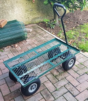
'My trolley', after living on the patio for years, has rather rusted out. It is
scrap or at least it certainly will be the moment I try to put 145Kgs of lathe
box onto it.
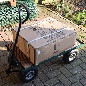
So old trolley went up the tip and new trolley, rated at 400lbs but narrower so
a more 'keep in the nice dry workshop' friendly size arrives.
Here's a picture of it with its fold up/down sides removed to be in a bit more
suitable for a heavy box. I also have some strips of 'decking board' that will
fill out the inside so it becomes nice and flat rather than that sharp
edge.
∗
When I said 'hoist' in the text above that was already plan B.
I was originally thinking that I could borrow the old engine 'crane' from Robin
but on checking
its
pictures I realised the whole design wasn't going to work in my
cellar. There is no room underneath things for its supporting legs (there is an
industrial sized air compressor under the bench) and very little room above for
its crane style arm.
I needed a magic skyhook. Sadly Ebay only supplied normal skyhooks.
Then I need some sky to bolt it onto but, thankfully, my workshop is a cellar
and the works of the floor above are fully open for access. I just needed a
couple of brackets. So I add some 40x40mm 3mm wall square steel tube to my
shopping list and reached into my toolbox for the really good tools.
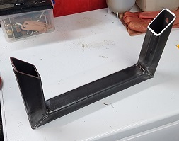
This is the first bracket. This one goes over the middle of the open floor
space to get the all round access. It is deliberately placed between two joists
so when it's not in use and the hoist is back in its box it can be swung up so
it is not a head banging problem.
So I cut the tubing to size. No, I didn't use a hacksaw. That would have taken
poor old me weeks. Yes, this is my video... but admittedly it is take three and
a switch from an Action Cam to the DSLR Nikon to pull a good focus.
Then I welded it up. I have recently migrated from decades on gas to a big arc
welder and, although I've been practicing, I'm still a bit of a beginner. My
welds here were not quite as good as I had hoped but, there again, not quite as
bad as I feared (penetration OK but a bit blobbly).
Then, finally, I put it up with some big M10 bolts.
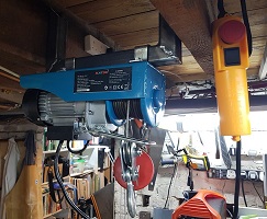
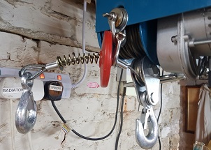
I have to admit it was a really cheap hoist because I was not expecting to get
much future use out of it. However the safety cut out limit switch plate had to
be removed and bent before it had a hope of working and if you looped the cable
back for double the lift the way they show in the manual the hook just fouled
with the cable on the drum. Also, as I have really limited head room, I needed
'right up' to be as high as possible to save having to get overly inventive
when slinging the lathe and their loop back plan wasted a lot of my vertical
space. However I do have quite a good selection of climbing, caving, diving and
boating gear to borrow from and, after a couple of tries, I came up with a
suitable solution.
The second bracket needed to be longer to allow me to do a traverse slide from
a spot right next to the bench, where the trolley could get to, onto the bench
itself so that both the lift and lower can be a simple vertical but the 40x40x3
tube is rated for that. This did however mean that it needed to go below the
bottom of the joists and clear the central heating pipes which implied that
after it has done its job it would have to come down until I need it again or I
would be putting dents in my head.
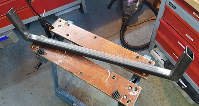
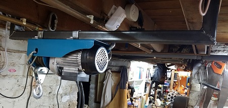
It went in quite well. When installed and wound 'right up' the throat of the
hook is 43cms above the bench. It's not actually a lot but by using the slings
thoughtfully it will be enough.
∗
And then I discovered that my two workmates, which are I must admit of very
different vintage, are different heights. It's only 5mm but, as the preparation
I need to do on them is all about level, this is a bit annoying. Clearly the
lower one is going to need a sheet of wood lain on it. I have something nearly
suitable. I can get inventive before it arrives now that I know there is a
problem rather discovering it with a lathe already swinging above things.
∗
And then, watching a video, I discover that the lip round the edge of a very
similar lathe's swarf tray goes lower than the part the lathe stands on. The
gentleman that found this mean little trick did a quite elegant job with a
router cutting a slot in his bench top for the edge to go into but I'm afraid I
went for the simple solution of cutting a big rectangle from the lathe's box
lid to go under the swarf tray.
∗
Interestingly this person also had a cut out for an oil/coolant drain in his
supplied swarf tray for which he had cut a matching hole in his bench top. I've
carefully inspected pictures of the DB10 and, thankfully, I don't see one
there. Hopefully I don't have to face that as it would never seal up so
something would have to be implemented below but that means I'd need access to
it even if it's only just to clear the swarf out occasionally.
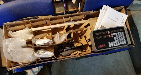 Well the first bit of lathe to arrive was a huge box of bits
that was the DRO kit.
Well the first bit of lathe to arrive was a huge box of bits
that was the DRO kit.
Actually I had rather anticipated that this would all come with the rest of the
lathe the following week so I looked at the delivery a bit suspiciously but it
clearly had my name on it. As at the time I was anxiously expecting a box with
two 40cm square fans in it and so this was a rather bigger than my
expectations.
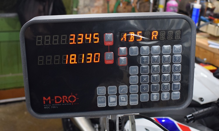
Anyhow the DRO looks rather fun. Naturally all my school lathe work was done
with callipers and a steel rule (good for ten thou) but now you can have
displays reading the position of the left-to-right and forward-to-back position
of the tool head to 0.005mm resolution (I will test for accuracy when it is
installed) so a lot of once hard things should become easier. Of course the
user manual rapidly gets to be a bit nonsensical without the hardware running
to try it on and the 'how to install' instructions make little sense without a
lathe to look at but everything appears to be within my capabilities. I can
measure carefully, I can drill holes accurately plus I already have the tapping
size drills required. Then I can thread the holes as I recently updated my
taps-and-dies set. After that it is just a matter of putting the parts together
to the diagram and doing the alignment which is just so much Meccano.
One thing that did worry me as I read through the installation guide was that
the longitudinal measuring sensor running along the back of the bed looks like
it will be right where I want to put the slings to lift things by. I worry that
it will get more than slightly mangled if anything slips. Also, after being
assembled from masses of individual parts and then set up with a dial gauge, it
does not look like something you want to dismantle and replace all that often
either. I wonder if I can fabricate a 'bolt on' sling point?
The run-up to delivery (aka the week before your tenth
birthday)
 When I said the DRO was 'the first bit of the lathe to arrive' I was rather
omitting the fact that I had started gathering together some of the
'essentials' already. I had bought a range of lathe tools and some stock round
stuff for my toy box. Wouldn't it be awful to get it all mounted up and have
nothing to cut and no tools to cut it with? Also I had some upgrade parts
either still on order and arriving 'any day now' or already sitting on my desk.
I had some lights, one to mount on the ceiling to shine down and another on a
magnetic clamp to go wherever it's needed. I also bought the grease for the
gears and the lubricating and cutting oils the manual advises.
When I said the DRO was 'the first bit of the lathe to arrive' I was rather
omitting the fact that I had started gathering together some of the
'essentials' already. I had bought a range of lathe tools and some stock round
stuff for my toy box. Wouldn't it be awful to get it all mounted up and have
nothing to cut and no tools to cut it with? Also I had some upgrade parts
either still on order and arriving 'any day now' or already sitting on my desk.
I had some lights, one to mount on the ceiling to shine down and another on a
magnetic clamp to go wherever it's needed. I also bought the grease for the
gears and the lubricating and cutting oils the manual advises.
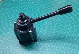
Then there is the 'Quick Change Tool Post' which clocks in at a wonderful
2.24Kgms, Robin would surely approve, and it is a delight to dismantle being
based around a multi-start left hand thread that has to be just right to get
both clamps in step and the handle pointing in a sensible direction when
clamped. To add to the fun it won't even fit without some machining. Oh yes,
the list of 'Ooo I want one of those' things would go on for pages but I ought
to wait and see how things pan out before going totally mad.
Robin had made sure both lathes came with face plates, they weren't listed on
the 'supplied' parts list, but are, he says, 'normal'. Either way one is now
listed on the manifest for my lathe. I have used one once but I think this will
mean I need some 'dogs' but they can happen later as you need them in the right
size range for the job you want to do and Amazon do lots on 'next day'.
When sorting the workshop out to make room for a lathe (aka throwing old stuff
away) I allocated three draws on the bench unit adjacent to the lathe site and
they are filling up already. There is also still quite a bit of stuff promised
as 'Standard Accessories' that will come in the box and that will need to go
there too.
Time for a minor whinge.
Some things perplex me a bit. Remember I may be 55 years out of date on lathes
but those are 55 years full of engineering. Why is there a guard over the
chuck? Is it just a way to make sure you take the chuck key out before starting
things up? Without the key in it the chuck top isn't a safety problem although
the chuck face, which must be unguarded, probably is.
Also the on-line illustrations show a funny plasticky thing getting in the way
around the tool post. This one I can't figure. I suspect it is the listed item
'chip guard'. The whole dangerous area of a manual lathe must be clear as you
need constant access to it and you must be able to see exactly what is going
on. Reaching round things will be more dangerous.
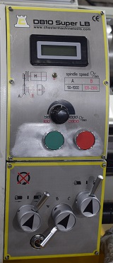
Also the silly cover over the stop/start buttons with a stop button looks like
it's only there to be annoying. There is a dirty great big red emergency stop
button right on the top already. Actually the buttons are in exactly the wrong
place, they want to be on the front so you can reach them when standing in the
place that gives you the best view of things starting up. The school lathes all
those decades ago had a lever so if something went wrong as you started up your
hand was already in position to stop it again at once. Expect a modification
coming up soon.
A lot of this just looks like 'Health and Safety Theatre'. Being seen to 'do
something' while actually doing nothing. Also if it comes with one (two?) of
those horrible self-ejecting chuck keys that now seem to be in vogue they are
going to meet the whirling blades of Dremel sooner rather than later. I've used
one once, it was first rate at ejecting and falling on the ways, or the floor,
but totally abysmal at chuck tightening. I promised myself 'never again' and,
seriously, I'll stick with that.
<sigh>
I'm probably just getting grouchy because I'm not good at waiting and it's
already late for my birthday.
 Lathe day!
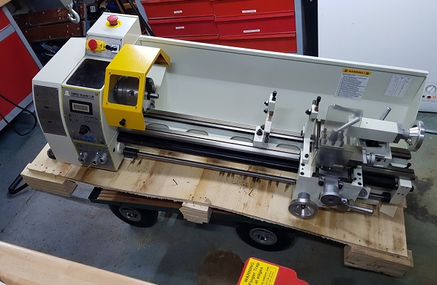
Well it came. It arrived on a ginormous pallet that held both it and its stand
with room to spare. We cut the straps and removed the stand boxes but still had
a dead weight that the driver and I could not move. So I knocked on next door
to borrow the big strong lads and unboxed it in the street, sorry - no video.
That made it light enough that all of us together could manhandle it onto the
trolley and let the driver escape. Then we dragged it round the back lane and
up the garden path. Once it was in the workshop it was stop and recover time.
Then, finally, I removed the base board, hoisted it and put it on the workmates
as planned. I lifted it by putting the sling through the holes in the bed
hoping that that would demonstrate a suitable lifting point that was more DRO
friendly but it needed some further thinking about as the lift point was just
below the CofG and it wanted to capsize.
By then I was pretty much worn out so I spent the rest of the evening reading
the manual, measuring up for the holes in the bench and, I confess, stripping
off the 'Health and Safety Theatre' items and bagging them up in case I ever
discovered I needed them again. OK I left the spindle for the chuck cover on as
it was further from the spindle than the lathe bed so it is unlikely to ever be
'in the way'. All this left my workshop a bit congested as the lathe's bench
space was now occupied by the base plate/drip tray while the lathe with its
workmates were taking up a lot of floor space.
The first serious problem I noticed in my reading was the tool height. It was
supplied with an old turret style tool post. I remembered these. Good for bulk
batch production where the tool setter sets things up and then the operator
just turns it to get the correct tool. Nobody in their right mind uses these
stupid things any more at hobby level where the usual batch quantity is one. On
the turret you padded out the tool to get it spot on centre height by putting
steel shims underneath. It has a set of tools but does it have any shims in the
box so I can try things when it hits the bench? Nope. Can I buy 'lathe tool
post shims' on the web quickly? Nope. <sigh>
So I put in the tailstock centre and then put one of the welded carbide tools
from the kit that came with it into the tool post and run them up to each
other. The tool is nearly 2mm low. <SCREAM> That wouldn't be
cutting: That would be ploughing (description of surface finish). So I try one
of my nice new indexed carbides that I bought already because their holders are
just a litle bigger. Not much better. I need some shims. Ebay has some steel
tape that might do but it's from Hong Kong and I'd get it next month. The
smallest metal in my box is some 1.2mm Ali but a model engineering site
suggests cutting up coke cans. I am truly horrified but I'll save some. In the
end I ordered two sets of guitar neck shims in brass and I'll try them (thank
you Google for your word searching). Hopefully that will tide me over until I
get the proper quick change tool post fitted and tool height becomes just
something you preset with a knob and then lock with a spanner.
The second problem, virtually existential for a mathematician, is the discovery
that the DRO considers that left-to-right (along the bed) is the Z-axis and
that fore-and-aft (radially) is the X-axis. Clearly lathes are intended to be
viewed when standing behind the tail-stock. This is going to be a sanity issue
unless I can be pretty Zen about it and consider that the lathe lives in its
own separate bizarro world turned 90° to reality. Actually it has already
confused itself because what is Z on the front panel is Y (up?) on the
back.
That, however, was it for another day. The DRO needs to be installed and then
the lathe can go on its allocated piece of bench and I will be able to get
through my workshop without squeezing between things.
But then things all started to go wrong.
Not the lathe, the lathe was doing just fine. I had a 'Me' failure. Well I'd
call can't eat, can't drink, can't sleep with retching and vomiting as a side
show pretty gone wrong. Also my back, that had been a bit stiff from all the
lifting the day after the delivery, but only in a grumpy old man sort of way,
was now transformed into a totally sadistic Dominatrix with the boots, the whip
and the cattle prod. Getting out of a chair took two hands and a carefully
planned roll. It was unimpressed by the idea of sleeping it off as dropping off
cued in horrendous nonsensical nightmares.
I still tried, I'm stupid like that, and this DRO isn't going to install
itself. I got as far as being told to replace two M6 bolts with M6x40mm grub
screws. So I combed through the parts spread out in bags, then the packing
lists and finally my personal bolt collection. Nope, Nope and more
Nope.
I could whinge to the supplier and he could whinge to his supplier and by
Christmas I might... Maybe I'll just 'Next Day' a packet of them from Amazon
and bodge it with some long bolts for now. So I order a packet of M6x40mm grub
screws and go and collapse on the sofa for a couple of hours.
Get up and brush my teeth as my mouth tastes like I've been gargling braising
flux in a subtle marinade of cutting oil. I'll just do the next bit and see
what it's like... I find a couple of M6x65 long bolts to screw it in. Nope.
Grab the Micrometer and, yes, that confirms that what is in my hand is an M6
bolt so where's the one that came out? Seeing them together the penny drops but
the Micrometer confirms: It was an M5. Get out an M5 long bolt. It fits.
Bother. Dive to computer. Amazon have already dispatched so it's 'too late to
change' but it was only a fiver so I order another packet of M5x40mm and I'm
still just in time for 'Next day' as well. I'm done. I'm going to bed.
Another bad night. You wouldn't want details.
A brain, addled with pain killers and lack of sleep, looked at an M5x40 grub
screw, in tight as instructed, and there were only about three threads
projecting and reasoned "I'm not putting a mission critical nut on that." Back
to the computer and somehow, in a moment of brain fade, ordered a packet of
M6x45mm on 'Next day'.
Well the next day I spent quite a while contending with medical issues then I
sat down at the computer, saw what I had ordered, the eyes rolled, I didn't
cry, quite, but I ordered some M5x45mm on 'Next day' at once. I'm going to have
lots and lots of weirdly long grub screws in my spare nut and bolt box after
all this. However this was the first day that I managed to eat a sensible
amount, drink enough to constitute life support and get more than a couple of
hours sleep so it rated as a pretty good day regardless.
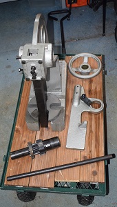
Next day, feeling a bit perkier. I started by fabricating the missing display
mount. The grub screws were promised but for later on...
They arrived! They fitted! I put a washer and nut on! Sadly they arrived at
8.15PM and I was already going wobbly so I decided to postpone the moment of
triumph, when I tighten everything up and align it, until the next day. However
I had counted everything else so all it appeared to need now was some slow and
careful assembly. Picture? It's the one at the back.
 Right. Another day and after breakfast the head unit is assembled. I've already
realised that this will foul the splashguard but that just means the
splashguard is going to meet the whirling disks of Dremel.
Right. Another day and after breakfast the head unit is assembled. I've already
realised that this will foul the splashguard but that just means the
splashguard is going to meet the whirling disks of Dremel.
I'm more concerned with how far left I can wind the slide. I need to be
reassured that the track covers that. I remove the chuck and try the centre and
its tip is 107mm from the head bearing block, the flat of the faceplate is
63mm, the lowest step on the 4-jaw chuck is 170mm and finally reinstalling the
3-jaw its smallest jaw step is at 125mm. These numbers represent the point
where any movement beyond this point, other than a drill or a boring bar, will
cause lathe to lathe contact and probably damage.
The slide on full left is at 100mm and the left hand edge of the a tool in the
tool post with the compound of full extent is 92mm. So I can crash anything but
the faceplate with normal tooling. I must remember that to do the full side of
something on the faceplate I will need a 30mm spacer. I can live with that but
I do need the DRO to run right up to the end stop. (The fact that the 'end stop'
is the slide running into the rather large coupler on the drive shaft when it
still has more teeth on the on the rack and even the lead screw so it could cut
my 30mm is another upgrade project for another day.)
It was many hours and not a few back-tracks to get the position planned,
marked, drilled and tapped but finally the carrier for the Z-position strip was
in place. Loosen the screws and it flops about enough to fine tune its vertical
line so the head is in the right position vertically and it has grub screws,
little ones this time, to push it out from the lathe to control the distance
the head flies over the track. In the end only one of the ten tapped holes
needed fettling which isn't bad for me. The investment in transfer punches and
occasionally panicking down the phone to Robin for technical support paid
off.
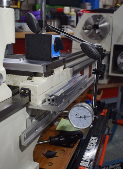 Another day and so fit all the grub screws in the mounting plates and start to
trim them for correct position so everything tracks. First perpendicular to the
bed, then equidistance down from the bed so the head moves in the slot without
deviating and finally equidistant from the centreline of the lathe so the head
stays an even, and small, distance from the encoder strip. The first is done
with a normal engineer's set square, the second with digital callipers but the
last with a dial gauge.
Another day and so fit all the grub screws in the mounting plates and start to
trim them for correct position so everything tracks. First perpendicular to the
bed, then equidistance down from the bed so the head moves in the slot without
deviating and finally equidistant from the centreline of the lathe so the head
stays an even, and small, distance from the encoder strip. The first is done
with a normal engineer's set square, the second with digital callipers but the
last with a dial gauge.
The first and last are relatively simple. You are making a measurement,
slackening a bolt, turn grub screws that advance 0.2mm/quarter turn,
retightening the bolt and checking your results. The second requires you to
loosen the screws holding the bar and reposition it with your fingers and
tighten the screws again. Frankly I did the second by measuring the highest to
lowest position range at each mounting plate then picking a number that was
within all their ranges, setting and locking the tail on the digital callipers
to that and using it as a feeler gauge.
Frankly the whole business was easier than I expected.
Then it was time to fit the strips, a magnetic encoder and a stainless steel
protective cover. The encoder is adhesive backed. I hate one slip and your dead
jobs like this so I started with a bit of OTT degreasing and then donned my
surgical gloves and fitted it.
Then remount the head and set the 'flying height'. Mine is on the gold standard
of 'three layers of post-it' (0.280mm to the Micrometer) and then I wound it up
and down stopping every ten cms or so to poke one of my post-it feeler gauges
under the head to assure no contact. Wonderful. Fit the cover. That, I thought,
was the Z-axis finished with. Cue sigh of relief.
 Confidence, they say, is that feeling you get just before you
understand the problem.
Confidence, they say, is that feeling you get just before you
understand the problem.
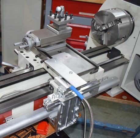
On starting into the X-axis stuff I found I had misread the installation
instructions by concentrating on the complicated drill/tap/adjust with
instruments stuff and rather glossing over the stuff that I dismissed as 'just
Meccano'.
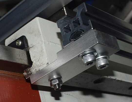
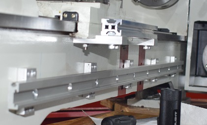
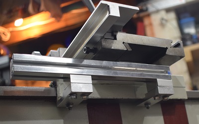
Firstly see my pictures above where the extrusion, which is exactly the
length of the saddle, has been carefully aligned with the saddle. Nope. Wrong.
Read the instructions idiot. This picture is how it should be. Up on blocks and
pushed over towards the tailstock some. Mia Culpa.
Secondly, and far more worrying, the left and right traverse of the
saddle is binding. Badly. Something is now way too tight on this. No obvious
villain so time for a dig. It's all going to have to come to pieces again.
<sigh>
The first wasn't actually much work. It was more awkward to get at now with the
encoder strip in place but by picking the right Allen keys it all happened. My
post-it feeler gauges were still on the desk which was handy as that piece
needed to be redone. It was, after all, just Meccano.
The second finally came down to my old nemesis the M6 to M5 switch out.
What had happened was that the old brackets had been a reasonable fit on the M6
grub screws so once everything was nutted up they didn't actually need to be
tight. The new M5 regime had slopped about so I had automatically tightened it
a bit more. However these grub screws were replacing the bolts that held the
ways together and they didn't want to be tight. After several ideas were
considered the best seemed to be to make the M5s as snug on their brackets, or
better, than their M6 predecessors would have been. This would take alignment
away from matters of being tightened up and into the domain of geometry. That
meant what I needed were some collars with a 7mm OD and internally threaded
M5.
If I just had a lathe it would be easy as I could just turn down some stock M5
nuts...
Health and Safety would probably warn you that lathes are not supposed to be
operated half dismantled and wobbling about balanced on folding woodworking
benches but at a pinch this was the little lathe that could.
After that I reassembled all the Meccano yet again and this time the position
of the extrusion was solid even with the nuts totally loose...
It's all rather good. Certainly the repeatability is fine but I'll have to
check the absolute accuracy later.
So that was all the 'all round access' preparation work on the lathe itself
done. A little Dremel work on a detail of the splash guard to ensure it cleared
the Z-encoder and I refitted that. It seemed prudent to take the DRO display
off and gather the cables together. It was then time to prep the bench.
Nothing demanding. I now had added the plate of plywood to go under the tray
with holes through the lot. Time for the move. So first the lathe was lifted
onto the trolley, then the hoist was moved to the long sliding bracket to get
things over the bench. Roll the trolley to under the hoist, lift and push.
That's push hard to make things slide over (should have put a bit of grease on
it). Lower.
It wasn't really that simple but as problems arose they were dealt with. It
ended up on the bench but my revised 'underlay' had outdated my original bolts
so some more longer ones were ordered. I was quite pleased that I had managed
to move a lathe of that weight all on my own and without further aggravating my
back problems.
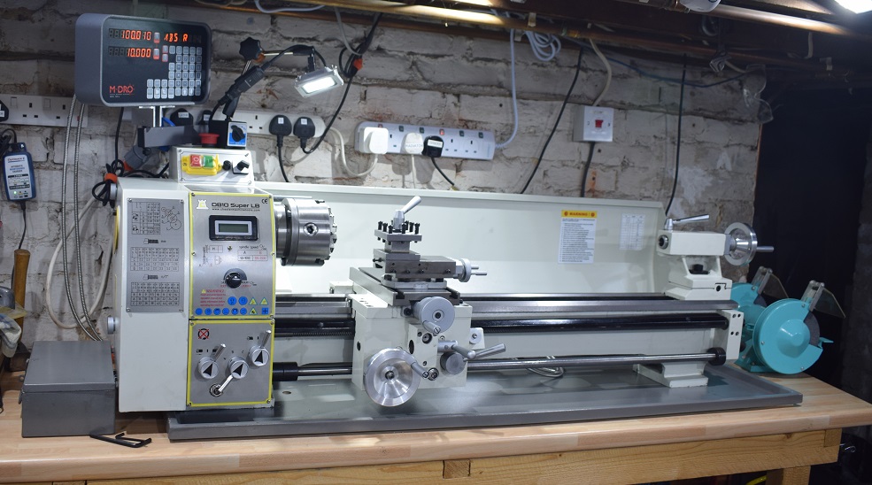
Let's have a baby picture. It was not even bolted down at this point, you can
see the holes, so it needs to move about 10cms to the right, and there were all
sorts of other details yet to attend to.
I even put it on the home automation list. Alexa gets it but still takes a
couple of goes...
Nigel: Alexa, turn on lathe.
Alexa: I'm sorry. I didn't find a device called Dave.
(Actually I never managed to fix this because it thinks 'Dave' is a TV channel
so I created a 'Group' in the Alexa app called 'Dave' and containing just the
Lathe switch and it works a charm now.)
Exploration...
 I made a thing. My first lathe thing in 55 years. It was only 22mm in diameter
but I didn't break much doing it. The surface finish was rather disappointing
but the tools I had are awfully pointed. However, although my drawing might
have only been a post-it held to the splashguard top edge by a fridge-magnet,
it was still made to drawing rather accurately. This is pretty remarkable as I
was still only configuring and learning how to use the DRO as I went.
I made a thing. My first lathe thing in 55 years. It was only 22mm in diameter
but I didn't break much doing it. The surface finish was rather disappointing
but the tools I had are awfully pointed. However, although my drawing might
have only been a post-it held to the splashguard top edge by a fridge-magnet,
it was still made to drawing rather accurately. This is pretty remarkable as I
was still only configuring and learning how to use the DRO as I went.
 Afterwards I even did my schoolboy cleaning up ritual, you got inspected before
class was dismissed, and all the peripheral stuff like that came flooding back.
It definitely needs a 'litter tray' under the bed so you just sweep everything
into that then pull it out, tip it straight into the bin, wipe off the oil
spillage and pop it back. Done. However that needs to be a close fit so it will
have to wait until after things are aligned and bolted down.
Afterwards I even did my schoolboy cleaning up ritual, you got inspected before
class was dismissed, and all the peripheral stuff like that came flooding back.
It definitely needs a 'litter tray' under the bed so you just sweep everything
into that then pull it out, tip it straight into the bin, wipe off the oil
spillage and pop it back. Done. However that needs to be a close fit so it will
have to wait until after things are aligned and bolted down.
The longer M12 bolts arrived so I fitted them. The tailstock end wasn't too
hard as I could use a rope and a lever to drag the lathe towards me into
position but that left the head about a centimetre forward of where it needed
to be so I re-rigged the hoist to fly it into position.
As getting the hoist bolts through the hanging bracket holes working by feel
over my head was a horrible job last time I used the grindstone to put a cone
on the ends of the bolts that I was trying to insert and that made the whole
fitting job go together reasonably quickly.
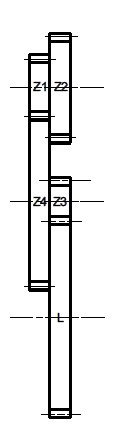
Then there was the matter of how to interpret the gear
selection tables that are helpfully printed on the gear cover and in the
manual but somehow the explanation appears to be missing. Finally I discovered
that H stands for 'packing piece' so no gear is fitted there at all. Gee
it would have been nice to write that somewhere in the instructions. In essence
a shaft with an H on it is an idler and on the 0.75mm thread both the
first and second shafts are idlers and they put in an arbitrary 50T gear that
engages with nothing on the second one because there are only two packing
sleeves in the kit.
Incidentally an M8 Socket Head Cap Bolt is so precise a fit as a drift for
removing the little sub-shafts that it really doesn't seem worth turning one
up. I left one in the tool box.
The formula for thread size is to work out the gear step-down from the 40T on
the spindle to the L shaft (multiply by the in gear then divide
by the out gear) then multiply by 3 to get the pitch in mm for gearbox
selection A. Then halve it for gear C and double it for gear
B. Ignore idler sub-shafts as in equals out and 50/50 or
such isn't even worth writing down. The bottom shaft, going into the gearbox,
always has a packing piece but sometimes it is the inside 'gear' and sometimes
the outside one.
eg: the first column of the metric table: where the top shaft is an idler gives
40/75 * 20/80 * 3 = 0.4mm
Applying it to the 18TPI entry where both the top two shafts are idlers do the
50T is a packer and the 60T cancels out:
40/85 * 3 = 1.41176mm then ÷ 25.4 and reciprocate gives 17.99166
I guess I can live with that. To get exact TPIs you're going to need a 127T
gear in the system (25.4*5) and that's a bit big but as you can see it can be
worked round.
The factors for feed rate are gear ratios from spindle to L multiplied
by 1.3222 give mm/rev. Annoyingly thread cutting gears are pretty much
incompatible with feeding. As before that's for gearbox A. For B
double it and for C halve it. Cross slide feed is at one third main
feed.
 And now I knew what gears did what I stripped the whole system down, cleaned
off the packing gunge in a bath of paraffin and cleaned and dried them on
kitchen roll. Then I awarded each gear its own labelled plastic bag and logged
its diameter as a shorthand for identification later as the stamps are barely
readable and I really don't want to have to count all those teeth again 'just
to be sure'. Finally I unpacked each gear in turn and gave it a profound fondle
in gear oil using a pastry brush to ensure it got the total gear oil
experience. (If that sounds needlessly erotic go talk to any old steam railway
enthusiast about oiling and the evils of rust on unprotected steel.)
And now I knew what gears did what I stripped the whole system down, cleaned
off the packing gunge in a bath of paraffin and cleaned and dried them on
kitchen roll. Then I awarded each gear its own labelled plastic bag and logged
its diameter as a shorthand for identification later as the stamps are barely
readable and I really don't want to have to count all those teeth again 'just
to be sure'. Finally I unpacked each gear in turn and gave it a profound fondle
in gear oil using a pastry brush to ensure it got the total gear oil
experience. (If that sounds needlessly erotic go talk to any old steam railway
enthusiast about oiling and the evils of rust on unprotected steel.)
I have to confess I'm not very happy with the swinging arm system that does the
screw cutting gears. The arm itself seems pretty standard but the funny little
spindles that carry the gears have some novel features. Since it gets no
mention in the manual I am left to try and fathom some reason behind the
slotted washers with cuts at different angles so they almost fit but not quite.
Also the matter that, I deduce, the back washers are different thicknesses so
you can pad the gears out different amounts so they don't grate on one another
is also a well kept secret. In fact without the exploded view provided in one
of Chester's competitors manuals for a lathe that is from the same source I
doubt I would have ever got it back together the first time within the duration
of my sanity.
Then there was the matter of the gear box oil. Now the manual tells you about
the threading/feeding gearbox and where the sight glass is, where the fill hole
and the drain plug are but it totally omits any mention of the one in the
saddle. However the one in the saddle is showing nice clean looking oil half
way up its sight glass so that's good.
Now I knew that it had dribbled quite a bit of oil at various points along the
way so far so 'nothing' in the feed and thread box's sight glass 'obviously'
implied it needed a top-up.
So I pulled the filler plug and started pumping oil in not really sure how big
the box was so not knowing how much was appropriate. At about the point where I
began to feel nervous about things it started coming out round the shafts. Time
to remove the bottom gear of the feed train, yes it's behind that, improvise a
catch tray that will fit under the body of the lathe (about 2cms) and pull the
drain plug. Once the flood had abated I noticed that the sight glass, still
full of oil, was actually lower than the drain plug so I pulled that out too
and let it run for a bit and then put it back and started cleaning up the
mess.
Well it finally settled nicely at about half way up the sight glass so that's
good but how you drain it I don't know. Conversely it has definitely been
flushed for now. What I was actually trying to do at this point was to condense
the 'Routine Lubrication' page in the manual into a few bullet points to be a
quick 'ready to go' checklist.
The last of the more procedural changes was to make the 'litter tray'.
Basically a tray to go under the bed so I can brush it down and then, rather
than fumbling about to retrieve the swarf underneath stuff just pull it out and
sweep it into the bin. It's only a piece of left over yellow Formica from the
first kitchen rebuild that's been propped up in the cellar for decades. I
hacked the shape out with the Dremel to fit round things and then added some
10mmx10mm plastic angle trim stuck on round all the edges, except the front, to
keep the swarf inside. It actually works quite well and my natural laziness
approves of things that make the chores more mindless.
I had hoped to add some start/stop switches in a more sensible (safer) position
but on investigation the circuit diagram supplied in the manual bears little
resemblance to the wiring or even the components installed. This means that my
planned modifications were irrelevant so that idea had to go on hold for the
time being. See my revised circuit diagram of the
lathe as supplied. The 'switch', annoyingly, is not a relay but a magnetic
latch on the 'On' button so it cannot be remotely started.
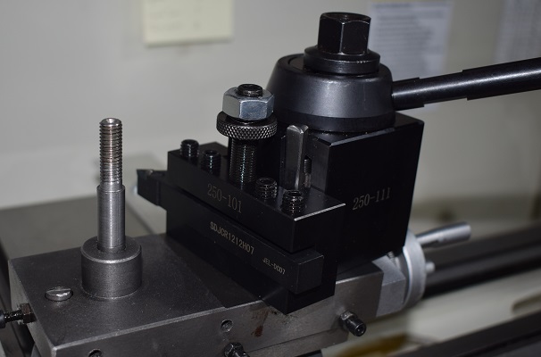
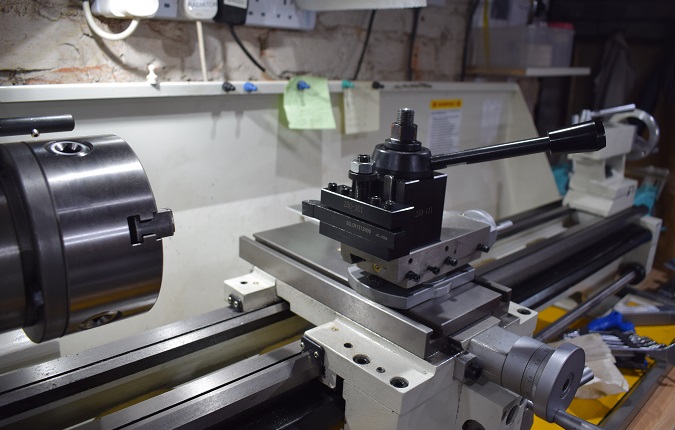
The next job was to fit the Quick Change Tool Post
(QCTP).
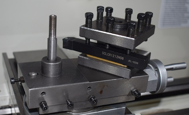
I had bought the Machifit 250-111 Chinese version of the AXA toolpost and a
bunch of 250-1xx holders so I could set up my tools for height and probably
even program their offsets into the tool memory of the DRO. This will mean I
can hot swap in a tool with the minimum of effort mid job. I chose the 'wedge'
type post over the 'piston' model because I felt the alignment was going to be
more predictable long term. I then browsed my way round the web looking for
other people who had done the same job already to see what ideas I could
adopt.
Well there seemed to be three families of solutions. 1) Modify just the
tool-post as touching the lathe is sacrilege, 2) Modify just the lathe as the
toolpost is too complicated and 3) Modify both. Also the level of 'other'
machine tools these people had at their disposal was widely different. In the
end I decided on my own variant of 2 that stayed within the tools I had and
knew and, importantly, it allowed me to incorporate a small trick so I had
provision to revert to the old Turret post if ever I found I had a job to do
that could benefit from it.
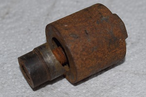
The Turret tool post was supplied bored to locate on the collar of the
Combination Slide and then it aligned against the spring loaded stud that comes
up from below to set its position. It had a 10mm shaft that became an M8 thread
to clamp it down. Below the slide it had an 18.44mm by 3.9mm thick 'bolt head'
that was prevented from turning by a 3mm roll pin.
(see drawing for details).
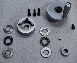
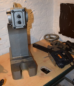
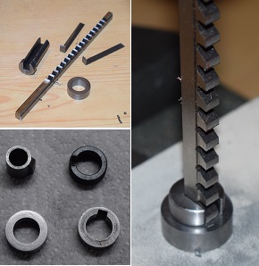
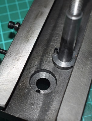
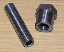
Here are pictures of the Turret post lifted off its mounting, then the QCTP for
comparison and then an underside view of the combination slide and the original
bolt.
The QCTP locks and unlocks its tool holders with its lever and is itself locked
in alignment to the Combination slide by a 14.2mm shaft topped with an 18tpi
thread (perhaps a 9/16" x 18 UNF?) with a rather posh nut that I'd like to
keep.
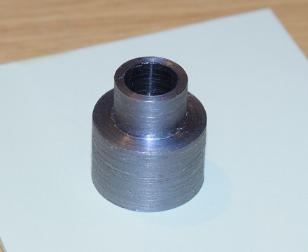
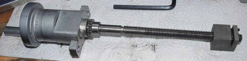
My plan was to drill out the hole to 14.2mm and then machine off the collar to
leave the top of the slide flat. Then I would fit the 'thing' I made (see
above). That has a 14.2mm diameter part to be a tightish fit on the enlarged
hole through the Combination slide and then a 22mm body to emulate the collar.
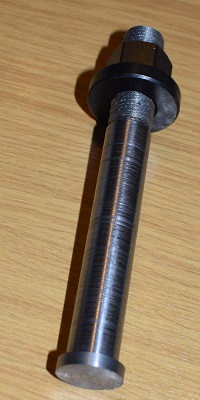 I then needed to make a 14.2mm bolt with a head to match the cut out in the
slide and turn an 18tpi thread on the other end to match the nut.
I then needed to make a 14.2mm bolt with a head to match the cut out in the
slide and turn an 18tpi thread on the other end to match the nut.
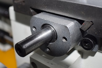
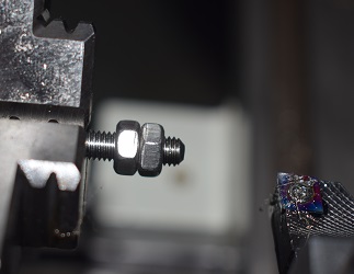
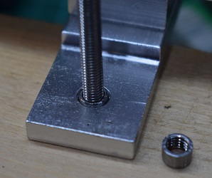
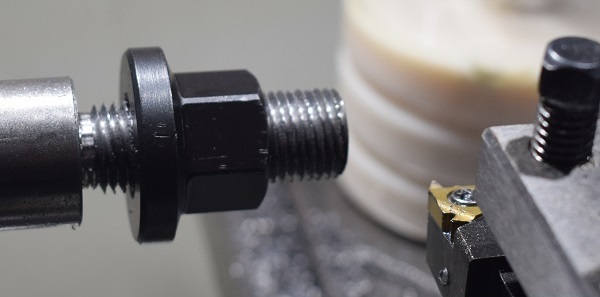 Here's the thread with the nut run on as a test. That is an 18tpi 55°
Imperial thread cut on a Metric lathe, something I have never done anything
like before. I did a dummy run cutting oversize so I could practice the
procedures then skimmed it down too the OD of the example thread I had and just
cut it until the nut went on. I will repeat it later when I have the QCTP
installed to reduce the chatter a bit and will also use the 'live centre' to
support the thread end and I rather hope that that will improve the surface
finish a lot.
Here's the thread with the nut run on as a test. That is an 18tpi 55°
Imperial thread cut on a Metric lathe, something I have never done anything
like before. I did a dummy run cutting oversize so I could practice the
procedures then skimmed it down too the OD of the example thread I had and just
cut it until the nut went on. I will repeat it later when I have the QCTP
installed to reduce the chatter a bit and will also use the 'live centre' to
support the thread end and I rather hope that that will improve the surface
finish a lot.
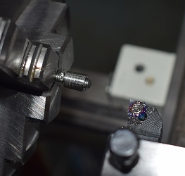
Once the thread was done I switched the gears back for a reasonable feed
rate and trimmed the long part down to the required diameter, parted it off,
reversed it in the chuck and formed the 'bolt head'.
The head is the original size and looks a little small but remember that its
function is to clamp the QCTP down onto the top face of the compound slide. The
diameter of the shank is a snug fit in the slide and the body of the tool post
to provide stability in horizontal directions. I will have to re-drill a
roll-pin hole in both bolts and the compound slide underside to ensure that the
bolts do not turn when being tightened up.
Finally clean up. Using a two inch paintbrush and sweeping everything into the
litter tray was just too easy. However I realised I was going to have to
reroute the DRO cables as their tie-downs are a bit of a swarf trap at the
moment.
Right. That was the easy bit done. Now I had to drill or bore out the Compound
slide out to 14.2mm and then machine off the collar without distorting the
flatness of its upper face. There were two ways to go about this:
1: My brother was now the owner of a new, large milling machine that I was sure
he would be happy to demonstrate it.
2: I could mount an adjustable vice vertically on the Cross-slide of my lathe
and do it myself with milling tools mounted in the headstock. I had bought the
accessory to do this but I had never used one before.
So I called to see how the Mill installation is going as I know Robin had an
engineer in that day to fix a problem. In a word: 'badly'. So I was going over
the next day to try and help out with that and also to try and mend a test
device he uses that is malfunctioning. I hoped I might get my Compound slide
machined if it all went well so I packed my lathe bits in a box and gathered my
electronics diagnostics gear together.
So off to Seaford...
 Well I started apprehensively as I was facing several unknowns but it turned
out to be a pretty good day. Within a few hours we had sorted the problems with
the test gun which certifies the Ballistic Chronographs and then fully
recalibrated it.
Well I started apprehensively as I was facing several unknowns but it turned
out to be a pretty good day. Within a few hours we had sorted the problems with
the test gun which certifies the Ballistic Chronographs and then fully
recalibrated it.
We spent some time examining the new Milling Machine and came to some
conclusions about why it was giving trouble and pulling out the overall ECLB
whenever you engaged the main drive.
Robin put my compound slide in the really big four jaw chuck of his new lathe,
we lined it up with a dial gauge then parted off the collar and did a finishing
pass leaving just about nothing outstanding. After that Robin fetched some
boring bars and turned out the centre hole to my new size.
Then, for a grand finale, we turned off the main electrical supply and moved
the feed for the Milling machine onto its own private ECLB and after that
everything seemed happy to stop and start without problems.
Three for three as they say.
I drove home feeling pretty pleased with myself, stuffed a frozen Pizza in the
oven, washed off the Compound slide in paraffin and then with the edge of an
engineer's square over the surface and a polishing cylinder in the Dremel
smoothed away the last of the collar. OK, I might have left it a few thou
dished but that is preferable to a bump as the outer edge should dictate the
alignment. Finally it was treated to the usual gear oil massage.
Après pizza I set myself to come up with a method to stop the new bolt
rotating when the nut on the top is being done up. I don't have the experience
to broach it for a proper keyway so, much as I don't like them, another
roll-pin seemed the way forward.
There was a slight hiatus when I discovered that my neatly compartmented box of
roll pins had suffered an in transit gravitational alignment anomaly and
had rather randomised itself but I needed a simple task to wind down after the
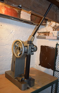
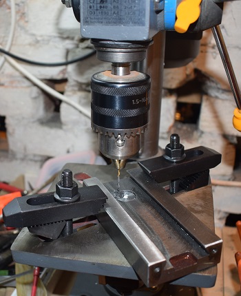
day and it's all sorted and labelled now. Then I clamped things to the drill
press (in the picture the QCTP is upside down below the table to act as a
spacer so I could tighten the nut) and then I drilled it 2mm.
There then followed my usual fight with roll-pins but we finally compromised on
a 2.2mm hole and it was still tight enough to need to be pressed in so it was
all together and I could finally assemble things. I confess that at the end I
was more relieved than pleased. Yes, there are still lots of things that will
need sorting out but that's what 'tomorrow' is for.
Time for further improvements
 OK. So far so good but now it was time to start sharpening up its act. For
instance if I took hold of my nice new tool-post and pushed it away from me and
then pulled it back towards me it went clonk-clonk. Zero the DRO and from clonk
to clonk it measured 0.510mm, although that was reading in diameter terms so
that represented 0.255mm of actual movement. Well that truly sucked. It was
coming to pieces again.
OK. So far so good but now it was time to start sharpening up its act. For
instance if I took hold of my nice new tool-post and pushed it away from me and
then pulled it back towards me it went clonk-clonk. Zero the DRO and from clonk
to clonk it measured 0.510mm, although that was reading in diameter terms so
that represented 0.255mm of actual movement. Well that truly sucked. It was
coming to pieces again.
 Annoyingly the 'how to adjust things' section of the manual tells you where the
adjusters are for the cross slide gib, hard to miss as they are screws sticking
out the side, but neglects to discuss the slide mechanism itself. So I phoned
Robin for some pointers.
Annoyingly the 'how to adjust things' section of the manual tells you where the
adjusters are for the cross slide gib, hard to miss as they are screws sticking
out the side, but neglects to discuss the slide mechanism itself. So I phoned
Robin for some pointers.
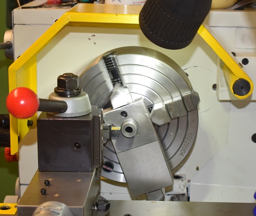
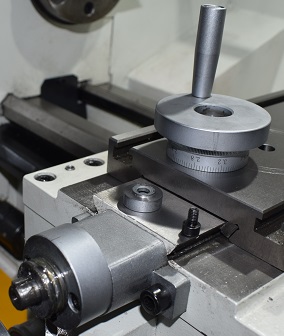
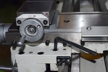
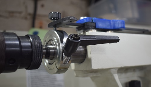
So here is a picture of what we are talking about. Undo the big Allen bolt in
the middle of the cross slide to free the nut and the two bolts that let free
the winder mechanism and the slide comes off its bed.
The rather cubical nut was threaded then slotted so the two grub screws are
there to basically distort things so you can tighten it up on the thread. My
grub screws were both loose so I very gingerly edged them tighter being careful
not to go too far and risk making the whole thing stiff. Oh and that's a left
hand thread. I'm not good with left hand threads. They contradict things I
engrained in my brain in childhood (Meccano again).
I rather resigned myself to going round the loop a few times and, as expected,
every time I reassembled things it was a bit better. In the end, with a full
oiling and greasing for good measure it was down to about 0.15mm on the
diameter DRO display and I felt I had squeezed everything out of the nut
adjustment and turned my attention to the winder mechanism.
Pulling the knob off revealed two thick washers and a thrust bearing but no
obvious provision for adjustment. There was a key that locked the knob to the
shaft but it resisted as much force as I was prepared to apply. Although it
didn't clonk any more and the bearing was full of grease but it just wasn't
tight. I cleaned it out as much as I could without a full dismantle and
regreased it and if anything that only made it worse so it might have been
harbouring some grit. I was only looking for some of the remaining 0.075mm of
movement so I really wanted enough of a shim to fill up the gap but not enough
to make things tight.
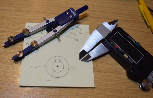
Well I drew out what I wanted as a template wondering what materials I had to
hand. It would be would go in a gap between a washer and the handle as all the
rotating stuff was done by a bearing. It was just going to be a gasket, a
rather thin gasket. So I cut out my drawing and tried that.
Well as one post-it gasket nearly halved the remaining slop I added another.
This made things just a fraction stiffer but the slop on diameter when I pushed
and pulled heavily was now less than 0.040mm with a tendency to spring back so
a better than ten fold improvement for the session. Uncompressed, unoiled
post-it, by the way, measured as 0.097mm on the micrometer.
It was better but it could be better still. I would have to come back to it
later.
 As I was putting things back together I wondered if I could find a way to cover
up the bit of T-slot between the Compound slide mount and the DRO sensor as you
just couldn't easily sweep out the swarf that inevitably got into it as it
didn't have an open end to push it through. While considering what I had to do
that it dawned on me that the idea was too obvious for me to have just invented
it so I googled for t-slot covers.
As I was putting things back together I wondered if I could find a way to cover
up the bit of T-slot between the Compound slide mount and the DRO sensor as you
just couldn't easily sweep out the swarf that inevitably got into it as it
didn't have an open end to push it through. While considering what I had to do
that it dawned on me that the idea was too obvious for me to have just invented
it so I googled for t-slot covers.
Google showed that I was right but that all was not going to be that simple.
For instance RS would sell me a 20 meter bundle of plastic stuff for £28
but I only want about 10cm. There was nothing on Ebay, the classic place where
somebody buys bulk and sells small at a mark up, so I ended up ordering some
10x10mm Ali U-section to experiment with.
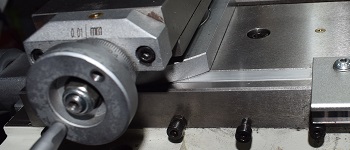
I needed to put a strip of Ali plate beneath it to bring it up to flush with
the surface from the 12mm deep slot but I'm rather pleased with the result. The
products on offer were mostly clip on plastic strips that sat on top of the
slide and would need to be cut to fit round things. Mine is just cut to be the
length to fit between the two T-bolts so the ends are well under the fittings.
As it is both a tight fit and flush with the surface that makes it pretty much
swarf proof and also an easy surface to clean over.
So coming back to it a couple of weeks later...
Well the slop was going back up again so this time I was going to pull out that
key and get right inside.
The key responded to a drift and a few gentle taps with a dead hammer and this
exposed a second thrust race so suddenly things made much more sense. The two
thrust bearings effectively 'pinch' the carrier, the collar with the three
peripheral holes on the left of the exploded picture shown with its rear side
up. The slop I am wishing to reduce could be in these two bearings but they
seemed much better when fully cleaned and regreased so perhaps revisiting the
thread and the nut would be in order.
As usual, when it went back together, with a generous fondle of new lithium
grease, the whole system was worse than before now scoring 0.3mm on diameter
and it was actually back to a having a slight clonk. However this time the hand
wheel felt really good so attention moved to the nut.
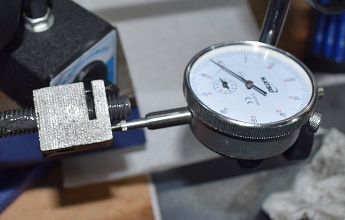
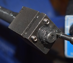
I took the nut out and I tried to set it up with the spindle clamped in a vice
with a magnetic dial gauge stuck to that. This told me that things still
weren't particularly good here but the initial test rig was too wobbly to give
repeatable numbers so it would be hard to make incremental fixes against that.
I pulled out one of the grub screws that were there to open up the nut's slot
to tighten it on the thread. It was a M4x12 and, as I really don't like their
flat screwdriver heads, I put some hex heads on Amazon to join my ever growing
grub screw collection but, sadly, I was too late for next day. What I did
notice however was that the slop I was measuring in the nut was about
0.12-0.17mm, so enough to account for all the remaining give in the system,
while that in the winding head itself was now at most about 0.05mm and I could
flex the test jig about that far with comparable force so it may well be
innocent.
Incidentally, looking for something to hold the nut for testing, its 23.4mm
smaller dimension is a great fit on a 'Half inch Whitworth' spanner from the
history tool box. I don't know why I find that amusing.
OK so the new grub screws came and I was definitely right about upgrading to
the hex heads. It was now much easier to edge up the tension in the nut so it
was just starting to go tight and then, when I reassembled it all, it measured
a mere 0.05mm on the DRO between push and pull and some of that 'sprang back'
when I stopped leaning on the tool post. This was definitely worth the time
spent reworking things and the wait for the grub screws to come.
Gadgets
Just a few things I felt would help...
A lamp on a stick-on magnetic base with a bendy arm. There is another matching
lamp screwed to the ceiling joists above, cashing in on this being a cellar
that I can reach up and redirect, but that isn't quite as 'go anywhere' as this
one. These are 'out-door' quality 10W mains powered LED lights as the usual
things they sell are just too wimpy.
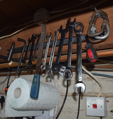
A magnetic tool strip to hold all those things you want to be able to grab for.
I bought a set of these and the smallest one is bolted to the inside of the
tool box to retain the small things that usually hide under the bigger things.
The roll of mopping up paper is just hung on a single 'shelf support'
bracket.
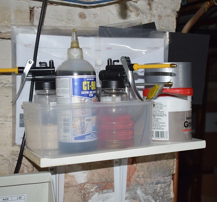
Finally a little shelf with my oil cans. That's ordinary soluble oil, posh
cutting oil for tapping and parting off, gear oil and some paraffin that I use
to clean up with some nice trigger style cans.
Carriage lock
 It was always considered good practice to lock the carriage when facing and
especially when parting off but it is a recognised problem with many Chinese
sourced lathes that this appears to be only supplied as an afterthought. You
will find plenty of YouTube examples where people have replaced the 'Allen key
bolt at the bottom of a hole' with a far more convenient lever to resolve this
annoyance. I thought I was just going to copy one of those.
It was always considered good practice to lock the carriage when facing and
especially when parting off but it is a recognised problem with many Chinese
sourced lathes that this appears to be only supplied as an afterthought. You
will find plenty of YouTube examples where people have replaced the 'Allen key
bolt at the bottom of a hole' with a far more convenient lever to resolve this
annoyance. I thought I was just going to copy one of those.
However... It turns out that my carriage lock 'bolt at the bottom of a hole'
isn't out in the open the way it seems to be for all these Youtubers. If it was
then this would make it a happy afternoon project where the most significant
design decision would be what sort of knob I was going to put on the end of the
lever. My bolt is tucked in right up close to the cross slide and the gib
adjusters actually pass over the top of it as you feed the slide in and out.
Frankly for a lot of the time it is virtually inaccessible, even to the
traditional sawn off Allen key. Also nothing I fabricate as a lever boss can
stick out above the surface for more than 6mm and still pass under those gib
screws.
So stage one of this project became to make it more accessible to use. Just
being able to manage it with a spanner at any point in the slide's travel would
be a huge step forward. A pretty lever could happen later.
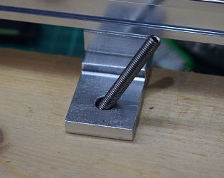
 So here's the drawing with the dimensions for what I
made. The part was turned from a piece of 13mm hexagonal bar stock so it would
take a standard spanner without the necessity to mill flats on it. The threaded
part was yet another long grub screw in M8 and cut off at 38mm. I deliberately
left the hex key head end on the grub screw intact and placed it at the top so
that if it ever does all fall to pieces on me I can just wind it out on that. I
had originally intend to use an M3 grub screw to lock the thread into the head
but with only a couple of mm of wall to work with I chickened out and sealed it
in with Loctite.
So here's the drawing with the dimensions for what I
made. The part was turned from a piece of 13mm hexagonal bar stock so it would
take a standard spanner without the necessity to mill flats on it. The threaded
part was yet another long grub screw in M8 and cut off at 38mm. I deliberately
left the hex key head end on the grub screw intact and placed it at the top so
that if it ever does all fall to pieces on me I can just wind it out on that. I
had originally intend to use an M3 grub screw to lock the thread into the head
but with only a couple of mm of wall to work with I chickened out and sealed it
in with Loctite.
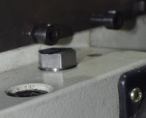
The second picture is of one of the gib adjusters passing over it . You can
just see how the 'nut' part stands proud above the surface so, when tightened,
it still bears on the bottom of its counterbore rather than mixing it with the
paint.
Doing the parting off as I finished it, as parting off tools are suicidal at
the best of times, I wanted to lock the saddle. Hence I had to wind the
compound out of the way to get an Allen key in. This is so much better already.
I would like a lever in the longer term but there will be complications. The
spanner shows me that although I only need a 90° swing to go from fully
locked to fully unlocked it needs to be the right 90° and I don't have much
room for an adjustable boss. Something using concentric parts perhaps but I
can only have 20mm of diameter total in the space...
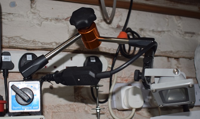
 Tool height setting aid
There are some very impressive tool height setting devices described on the
web, often with extended YouTube videos of them being made. It all looks so
much fun to create something complex but I really don't have the time. I just
want a quick and effective solution to give me an easy but accurate way to
setup a tool tip on centre and I want it now.
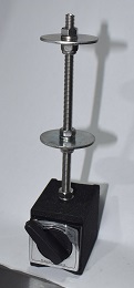
So here is my solution. It is a small mag-mount holder that I already had, I
admit when I first saw it I wondered why it was only £8 on Ebay but it
did the job it was sold to do but wasn't quite strong enough for what I was
planning. However here small is just what I want. Screw in a length of M5
threaded rod, add some penny washers and nuts and there you have it.
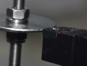
The two tiers are there so I can either stand it on the lathe bed or on the
cross slide and let the tip of a finger feel for the edge as I go from the
washer to the tool. Poking about with a dial gauge confirms what I suspected
that my fingers are very sensitive to a step like that. OK, setting it up was a
bit of a fiddle but the M5 thread only advances 0.8mm/rev and using flanged
nylocs underneath the washers to help promote 'level' helped. I set it up
against the MT4 Centre in the Head Stock. Again it is easy to verify that is
running true and then just run the gauge up to it and set the top face to the
point.
In use it places you within a fraction of a mm in moments on the QCTP carriers.
I prefer it to tricks like trapping a short steel ruler between a round work
piece and the tool or similar methods. Actually I'm not convinced that getting
better than a few tenths is relevant. At 1cm radius 0.1mm represents about
0.5°. Who makes inserts or other tools with faces critical to less than
1°?
Power switching
 As I have already intimated I did not like the power buttons up on the top of
the Headstock at the best of times and seeing the power lever on the Saddle of
my brother's lathe just reinforced the point. Certainly reaching up and over
things, especially for 'STOP', had to go.
As I have already intimated I did not like the power buttons up on the top of
the Headstock at the best of times and seeing the power lever on the Saddle of
my brother's lathe just reinforced the point. Certainly reaching up and over
things, especially for 'STOP', had to go.
I did wonder about putting switches on the Saddle to mimic Robin's lathe but
decided it would be too messy and there was no obvious way to emulate the lever
mechanism. However, hitting a lull in getting parts for other jobs in the run
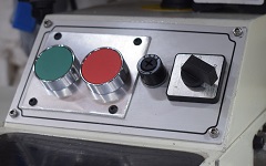
up to Christmas, I pulled the front panel off, burnished out the
warning logos (did the man in the hat one really
mean that I should wear a helmet to operate the lathe?) and fitted two buttons.
The red one is a normally-close type and was just wired inline with all the
other cut-outs while the green one was only there because I didn't want to have
to come back later and cut another matching hole. (I punched the holes B9A size
because I just happened to have a punch handy in that size and then opened them
up the last millimetre or so with an abrasive thing in the Dremel.)
That gave me a STOP function but I still had to START things with the button on
top so its magnetic latch could hold it on. What I really wanted was to have a
proper relay system, just like the one in the manual, so I ordered a suitable
relay, well two, and some nice DIN rail to mount it on so it's
official.
There is a problem with all this however. My lathe lacks easy rear access. It is
backed up against a wall and although I can remount the hoist and unbolt the
lathe from the bench and slide it out to do any big time repairs I didn't
really want to be doing that just for detail wiring tweaks. However since what
I wanted to do was rethink the wiring on the switch and the switch comes out on
its panel I could probably access everything important through there. If I were
to mount the relay in the front compartment that would do it nicely. That might
also mean new switches on the top as I didn't want to pull the existing switch
apart to see if I could reuse it in case it didn't want to go back together. So
I ordered some more matching buttons. They were only £8 the pair.
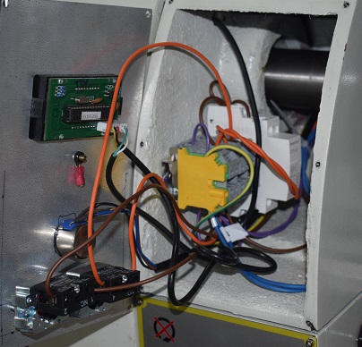
The wiring for the relay is quite simple. The Neutral would connect directly
while the live, after passing through all the safety interlock switches in turn
would go through both Start buttons and the relay NO contacts in parallel. The
output would then feed the motor and also the relay coil. The relay coil return
line would pass through the extra contact set on the Forward/Reverse switch so
it automatically drops out if you try to switch direction on the fly. The
amount of wiring needed appeared to be relatively minimal.
Here is my sketch of the wiring changes
I implemented it on the DIN rail with bridged connections make all the external
screw down contacts 'single wire' and the DIN relay block. Since the original
magnetic latch switch wouldn't work in this system I replaced it with two more
pushbuttons on a filler plate.
While I would have liked a lever it just looked too much work to implement.
Tailstock DRO
 Originally I thought that the engraved scale on the tailstock spindle would be
sufficient for the sort of work I would be doing but my first attempt at
drilling to an accurate depth cured me of that delusion. You needed just the
right light to even see it and, as the only reference was the edge of the
tailstock casting, which hides the section of scale to come, you end up having
to count the lines where normally a glance, seeing both ends, would tell you at
once that that line you are on is number seven. Putting the point of a drill at
2mm from the line that I wanted to part off at was a bit edgy.
Originally I thought that the engraved scale on the tailstock spindle would be
sufficient for the sort of work I would be doing but my first attempt at
drilling to an accurate depth cured me of that delusion. You needed just the
right light to even see it and, as the only reference was the edge of the
tailstock casting, which hides the section of scale to come, you end up having
to count the lines where normally a glance, seeing both ends, would tell you at
once that that line you are on is number seven. Putting the point of a drill at
2mm from the line that I wanted to part off at was a bit edgy.
A common trick I see on the web is to use the works of an inexpensive digital
calliper (Google 'diy tailstock dro' and look at the pictures). The cheap
plastic 0.1mm resolution version is more than adequate for this job. It just
needs fixing politely to the tailstock. This is, as ever, not always as simple
as you would hope.
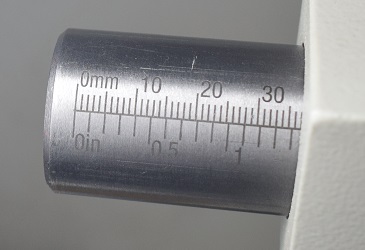
My tailstock spindle winds back in to flush with the tailstock face, the first
1.3mm as it extends is a chamfer and at about 5mm out the engraved scale starts
and you are in the working range. The engraved scale counts up to 65mm (ie 70mm
extended) and it runs off its thread at about 74mm. Winding back in, however,
it ejects its client MT2 taper anywhere from flush (for the live centre) to
about 13mm extended (for the drill chuck). This sets a limit on the design for
the spindle attachment. If I use a collar on the spindle it has to come off
easily to allow me to eject the live centre or anything else with similar
geometry.
Since my tailstock is rectangular I decided the scale was to go on the top for
lighting and visibility reasons. I then I located one of the callipers I had
that didn't have a tail for measuring holes, always an annoyance, and appointed
it as DRO. The first check was that, if placed on the top of the tailstock, did
the locking handle clear it? Yes. Great. Then I sawed it down to size removing
the lower jaw and lower tang on the part with the display and shortening the
slide so it was clear of the tailstock wheel and winding scale. This still left
me able to read 91mm from stop to stop. (If you do this fit a replacement end
stop quickly, I used an M3 nut and bolt. You will learn nothing useful in the
time it takes to put things back together if it comes
out.)
So the whole job really boils down to two questions:
1) How do I attach the readout part to the Tailstock?
2) How do I attach the slide part to the Spindle?

 I reasoned that the readout must be the easy part so I tackled that one
first.
I reasoned that the readout must be the easy part so I tackled that one
first.
A good solution, used by many, is to just glue it on. Use the right glue and
that is several problems solved in one. Annoyingly I have a Tailstock oiler
point in just the wrong place to make that a good idea.
I sat down and designed an aluminium bracket that would spring everything into
alignment but it was too complicated for me to fold up with the tools I
had.
After several other ideas failed and starting to get annoyed with the whole
business I glued two rather strong magnets to the bottom of the display module.
However even Araldite couldn't stick a heavily chromed magnet to a fresh carbon
fibre surface so they took it in turns to fall off until I had a total sense of
humour failure and gouged the surfaces with attitude to help key in the
glue.
However... I was also setting up the milling attachment (see below) at this
point and it slowly dawned on me that the Tailstock didn't need the display
part wonderfully aligned, just straight. The magnets were good at that - click
it on and push it so the tail is parallel with the side. If I didn't do
anything other than that it could go on the milling attachment too. All I
needed was compatible connections to the slide part. Neither of these units
care a hoot about absolute position as I'm going to hit the zero button anyway.
Also this means that if one of the magnets falls off again I don't need to
worry about putting it back exactly to match some fitting just slap on some
more glue. So it was time to move on to sorting out the other end and perhaps
just make the bit on the callipers very simple and have the more specific bits
fitted to the Tailstock. I'll cover the Milling slide later.
How to attach to the TailPost Spindle? In an easy to remove fashion?
After some consideration I bought a cheap 30mm Split Shaft Collar on Ebay and
some M6x32mm clamping handles on Amazon and turned up a 12mm long collar to
move the clamping face out of the counterbore so the clamping handle would fit.
The clamping handles are a favourite toy of mine as it means I can have a lever
to tighten things up and then stow it in whatever direction is least 'in the
way'. Then I drilled and tapped for an M4 bolt at a point that would place the
handle nicely if it were the top and drilled the calliper head to match. Since
the callipers are attached by magnets it is very easy to line them up to pop
the bolt through then straighten it up so it is inline with the tailstock
axis.
I'm rather pleased with it. It is quick and easy to fit and remove so it isn't
going to be in the way and the slop is less than one count so I have tenths
of a millimetre which is more than adequate.
Yes, I did need to put a couple of washers under the Spindle locking handle to
ensure that when it tightened it was not neatly over the display. Also note
that the pictures were redone after the Milling attachment was sorted so they
show the callipers with the jaws fully cut away and the nice M4 finger screw to
attach to the lathe fitting.
Milling on the lathe
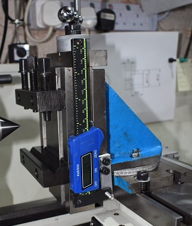
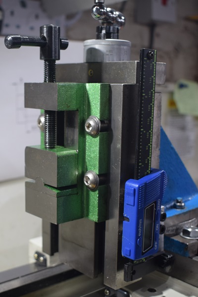 This is, admittedly, cheating but it's a good sort of cheating. The lathe has a
big, very rigid base. It already has two axis DRO. It has a big motor to turn
things. All it needs to do is to reverse it all about, put the tool in the
spindle and mount the work piece on the slide and you have a mill. Well
obviously not really but I can, at least, manage a good enough approximation to
a mill for a guy who only wants small, detail work and has no room for any more
serious machine tools.
This is, admittedly, cheating but it's a good sort of cheating. The lathe has a
big, very rigid base. It already has two axis DRO. It has a big motor to turn
things. All it needs to do is to reverse it all about, put the tool in the
spindle and mount the work piece on the slide and you have a mill. Well
obviously not really but I can, at least, manage a good enough approximation to
a mill for a guy who only wants small, detail work and has no room for any more
serious machine tools.
The first thing I needed was a metal holding vice that could move vertically in
a controlled fashion but, as this 'milling on a lathe' idea is quite popular,
these are readily available. Now I will confess that I bought a rather cheap
one that claimed it was Myford Compatible and didn't look at the details too
carefully. I suspect it was cheap because it had been in store for a while and
it needed a bit of work to get it back up to code. This was going to be more
than a simple clean and oil. It offered me a vertical plate 100mm wide and
160mm high with two vertical T-slots that take an M10 T-nut. The wheel on the
up/down (Y?) feed drives at 2mm per turn and has a nice scale in tenths and
surprisingly little backlash. It only really has about 55mm of vertical travel
before it starts to get a bit sloppy but I suspect you can work round that. It
came supplied with two bars that, when bolted to the face, act as a 30mm deep
vice and the lower one has a V-slot for round material on one side.
However taking it to pieces showed more problems. It had a rotating base with a
scale marked in degrees but no reference line. Now as there was no inherent
precise way to locate it this might have been good. I took some T-nuts and
clamped it to the lathe cross slide with M8 pan head bolts pushing it hard
backwards as I did it up. This is now my nominal zero so I scribed a reference
line and put some ink in it.
Annoyingly somebody had thought it appropriate to paint over the nuts that you
needed to release to turn it on this scale so they had to be removed, the bolts
wire-brushed and then cleaned up with a nice Presto die. I threw the nuts away,
I have plenty of clean, unblemished M6 nuts to replace them with.
Then it was time for a clean, including removing the many burrs still on the
edges and a brown stain where the 'vice jaws' had been sitting. It wasn't rust,
it just looked like congealed oil but I didn't think oil congealed but perhaps
packing grease does. A little gentle attention with a 400 emery got it off with
the usual wash afterwards to make sure I don't leave any grit behind. Once it
had had that done then it received its introduction to my gear-oil regime we
were ready to think about installing it.
Well as I already mentioned the Tailstock DRO calliper was targeted for a
second job as Y-axis DRO. This time it sticks to the slide and is attached with
a 4mm bolt to an extension plate on the base. Its position has to be slightly
convoluted to avoid the gib adjustment screws. Of course once the position of
the final hole was selected the remaining bits of the calliper head that
weren't needed could be sawn away and some nice finger friendly bolts could be
bought for the attaching screw.
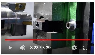
Nothing was seriously complicated other than the annoyance that the T-nuts I
had intended to attach the base to the slide actually projected 1.5mm above the
surface which made making things go flat a problem at first. Thankfully I had
some M8 T-bolts that fitted in these slots and held things satisfactorily
rigid.
The cutting range is, of course, very restricted compared to a proper mill but
if I am careful to mount the base at 66mm from the front edge of the slide top
face then the centre point of the spindle can traverse just over the whole
100mm width of the plate and there is about 80mm of usable vertical travel from
about 20mm up from the bottom edge of the plate. It will go further down but it
might be difficult to clamp there and the gibs are beginning to run out of
overlap so some slop is beginning to be evident.
Once it all looked workable the real consequences of not choosing wisely began
to become more evident. The apparent 'vice' really wasn't one. It was just the
usual trick to clamp round stuff in the range 10-32mm diameter edge on, well
provided it was at least 50mm long. Probably quite good to put in a keyway
though. It would also take a lump of rectangular stuff that was big enough for
the clamping screws to hit but anything else was going to require me to get
inventive. I hunted round and bought a small vice as all I expected to do was
small parts. Bigger stuff would just have to be clamped.
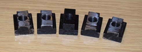 Well the vice came and it needed to be clamped into the T-slots. The M8 T-bolts
that I had were intended for a smaller slot and although I had both M8 and M10
T-nuts for this slot bottom size they were again too tall, projecting about
1.5mm out of the top. Frankly the T-slots were more suited for an M10 but the
vice was slotted for an M8. Well... It was probably all really imperial but
let's not crash and burn with the Mars Climate Orbiter. The best move would
probably be to face off some of the M8 T-nuts I had so that ordinary M8 washers
and bolts could tighten the vice onto the plate. I just need a temporary fix so
I could do the facing off.
Well the vice came and it needed to be clamped into the T-slots. The M8 T-bolts
that I had were intended for a smaller slot and although I had both M8 and M10
T-nuts for this slot bottom size they were again too tall, projecting about
1.5mm out of the top. Frankly the T-slots were more suited for an M10 but the
vice was slotted for an M8. Well... It was probably all really imperial but
let's not crash and burn with the Mars Climate Orbiter. The best move would
probably be to face off some of the M8 T-nuts I had so that ordinary M8 washers
and bolts could tighten the vice onto the plate. I just need a temporary fix so
I could do the facing off.
Well the supplied round stuff clamps were on M6s and they are the right height
so I decided to borrow them and found matching M6 bolts and some big washers. It
all went together reasonably easily although doing it flat on a bench where
gravity is not snatching for the T-nuts would help.
So I skimmed 2.5mm from four of the five M8 large T-nuts I had in my T-fittings
box. It was a bit of a steep learning curve as I hadn't done anything like it
before. However it worked, With some round headed bolts so they stay below the
back face which allows more flexibility in packing pieces I now have the right
clamp down for the vice. It needed a run over with the dial gauge to get it
aligned to the bed but that's another part of the system sorted.
An aside on my Arbor Press
I have struggled with things that needed squeezing and the lathe opened the
need to squeeze even more stuff. Jiggling things into a vice and trying to hold
them in a horizontal line while I wind it up has usually failed. Gravity is not
always my friend.
So I decided it was time to buy a proper vertical, pull the lever, Arbor Press.
I worked out how much opening I wanted and searched pretty single mindedly for
that. Most of the cheaper ones I saw were too small and, as I want to drive
broaches for keyways, it needed to open quite a long way. Finally I found one
and it wasn't as expensive as I feared. Magic. So I ordered it at once.
It arrived on a truck on a pallet. Gulp! I had somehow naively imagined it
would be somewhat smaller and lighter when I chose and paid for a big throat.
However the new trolly was ready to bring it round and up the garden. What was
that Robin told me about bulk cast iron for rigidity? 56Kgs so I assume he
would approve.
This is not a complaint as it should do everything I want or need and more
but I just can't help going all physicist on things. It's in the blood after
all these years I suppose.
Measuring at the shaft... it moves the ram 15cm/revolution.
The arm is 55cms long so say I can realistically apply a load at 50cms from the
axis and the circumference of a 50cm radius circle is 314cms.
I make that a mechanical advantage of 314/15 so 21.
So with the arm horizontal and me (70kg) pulling hard enough to lift my feet
off the floor I'd only get 1470Kgs.
So I'm going to need an extension to the arm, or a fat mate, to reach its rated
3000Kg. Thankfully I have some of the 40x40x3mm square steel tube left over
from building the hoist mountings.
Not that anything I've done so far needed more than a gentle, one handed pull
and the ratchet means I can set the arm at a suitable angle to swing on it.
However I did discover that I did need to bolt the press down to the bench as
it tipped up quite easily despite its weight. I fitted some M16 bolts and added
a piece of timber between the back of the bench and the joists above that
support my kitchen to discourage the bench from tipping.
To test things I tried making some spare spacers for the lathe's
feed/threading gears, the H part, but with a bit more outside diameter and not
quite such a 'hammer on' fit. I turned them up and drilled them but my 14mm
drill was a fraction undersize so I needed to ream them out to get a nice 14mm
finished. Then I discovered that the part was way smaller than the smallest,
25mm, slot in the press's aperture plate so I searched out a piece of
125x60x8mm steel scrap which felt heavy enough to be up to the job and drilled
it out to 15mm to use as a sub-aperture plate.
Then I set everything up and ran a 5mm broach down through both of my blanks. I
think they came out rather nicely. In the picture the top two parts are a
supplied keyed shaft and the one spare 'H' blank. The bottom two are my two
parts taken after the broaching and then checking the first one.
Other Entertaining Tools
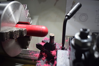 The 'ball cutter', a device to turn a convex or concave 'face', is
rather fun.
The 'ball cutter', a device to turn a convex or concave 'face', is
rather fun.
This is a rather cheap one and is perhaps is just a little sloppy as a result.
It consists of a cutter that can be swung in an arc so as you advance either
the carriage or the saddle you go from just nicking the corner of the stock to
cutting the full curve. Properly managed it can cut a ball but the sequence for
that is to tap and drill the blank first then mount it in the chuck by its
screw and then advance the tool sweeping to get the desired result. It is a
load of fun to get the adjustment spot on to get the size of the ball to fit
the required position exactly.
The diameter of the ball is set by the position of the tool holder along its
swinging arm so it can be a little messy to set up and the lever needs to be
adjusted so as not to get in the way of things or feed your fingers into the
chuck. The use of a symmetrical tool holder with a double ended carbide insert
allows you to cut both inside and outside radii quite easily. I mounted it in a
conventional QCTP holder so it swaps in and out nicely and preserves its centre
height. This is one of the systems that really benefits from a finishing pass
with coarse then fine then very fine emery paper while it is still rotating in
the chuck as on high visibility parts like handles and especially on coloured
plastics the dimensions are probably not critical but the finish is
everything.
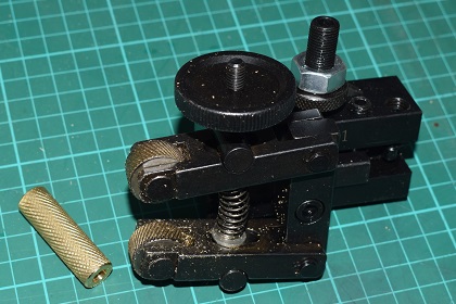 The 'knurling' tool, the thing that puts that nice grippy surface
pattern we are all familiar with on metal parts.
The 'knurling' tool, the thing that puts that nice grippy surface
pattern we are all familiar with on metal parts.
My school-boy introduction to knurling was based on a simple one wheeled tool
where you simply forced it up against the surface to cut in a way I thought
most unsympathetic to the saddle positioning nuts. This model is described as
having a 'scissor' type action so the metal forming pressure is applied by
tightening the wheel on the top of the tool rather than advancing the slide.
Again I chose to mount it on the QCTP for convenience and to ensure it is
consistently perpendicular to the cutting face.
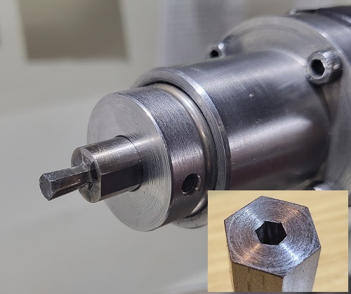 The 'Hex Drill'
It is always fun, when showing off some of your work and somebody comments on
the hexagonal hole, to just look at them blankly and say "Drilled on the
lathe?" as if you don't understand the problem. So, just to give an example,
here is my hex drill and the hole it just drilled. I like it as I much prefer
using Allen keys to tighten things up or adjust them over slot style
screwdrivers (for example see the comments on the Cross slide modifications
above).
I like the hex drill, properly known as a 'Rotary Broach', because of its
simplicity. It is a slightly tapered tool with a dished front that is set in a
free to rotate bearing but inclined at about 1° to the axis of the lathe so
the cutting edges are always rocking on the work piece. As you advance the
tool they cut in putting a hex finish in your predrilled hole (I drill it for
the 'flat' size of the hex key).
I have a few sizes of hexagonal cutters but I worry slightly about getting
replacements. My broach takes cutters with a 10mm shank while the ones I see on
offer are either larger or smaller and blooming expensive. I have instructions
for making them up but it involves accurate milling, grinding and a proper
dividing head. Humm... Sounds like an excuse for more toys.
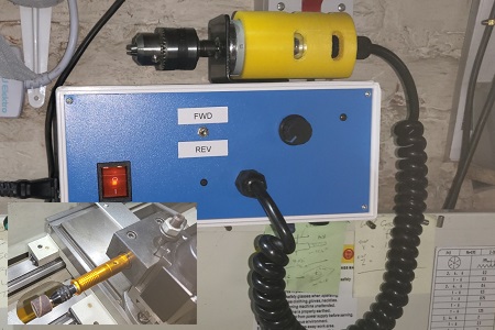 The Grinder
And finally there is this little device. Basically an electric motor with a
PSU/speed regulator shown in the inset driving a flexible shaft to a Dremel
style chuck mounted in a QCTP tool holder block.
I've had a lot of success using the Dremel hand tool to do shaping and detail
forming operations so I have built, what is basically, a Dremel as a lathe
tool. This brings the accuracy of the DRO to what has always been a hand tool
up until now and it does a lovely polished finish running fast against a slow
turning part. The motor is only 35W so hardly great cutting power but I can
wait.

By Nigel Hewitt