HOLD THE BUS!!
Fitted as standard? Huh? Where are my screwdrivers?
Take off the covers and release the front panel and sure enough. There it is snuggled in behind the front panel with the plugs hanging loose in front of it.
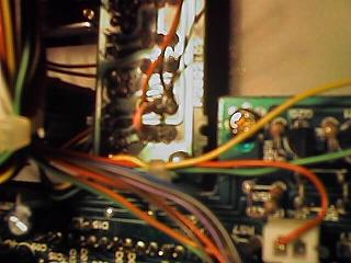
Get the service manual out and trace back the electronics....
The CTCSS and tone burst modules don't seem to interact at any obvious level except that they share the same T ENC switch. Not that they share the same wiring but one module is switched by one half of the switch and the other module by the other half. The function of the switch depends on what module is fitted. It appears that when the '767 was designed Europe used 1750Hz tones at the start of a transmition to activate a repeater and the USA used subaudible (67 to 91.5Hz) tones running all the time. Yaesu fitted one switch for Tones and sold you the module to suit. So what we need is an alternative switch to control the tone burst. Now that's a problem as the '767 is just too pretty to drill a hole in the front panel and pop in a cheap toggle switch so which switch don't I need?
It has to be Dial lock. Why do I need to lock the dial? OK so I'm clumsy and it does come in handy some times but I can live without it. It doesn't get another mention in the manual so I hope it's not got some secret set-up function that I will need one day.
Buzz them out. Red goes to ground when the switch is ON and brown when the switch is OFF so that matches the wiring diagram. The switches seem to be illustrated in the inactive state so this is negative logic.
Now the D LOCK switch is a change over just the same but it's more complex. You can see the higher three pins are the ones that drive the panel LED but unfortunately it has a track routed through one of the lower set that control the dial lock. The dial system is O/C to unlock so all I have to do is cut the tracks and the dial is unlocked forever.
The right hand contact is made in 'OFF' and the left hand in ON so right is brown and left is red. The ground connection is fortunately on the centre pin of the other side of the switch so it is just a short link between two adjacent pins.
Finally take some pictures and then reassemble it all. This is the point that I am pleased I colour coded all the plugs for the linear amp and the data modes and then put a picture at the back of the manual.
Fetch the handy for a quick check...
Yes, beep and no beep dependent on the D LOCK switch and it has a nice red light to warn me I've left the tone on.
NB: I haven't included instructions for opening the case and accessing the back of the front panel as it is all covered quite well in the maintenance manual. If you've got a rig of this complexity and you haven't bothered to get the tech manual for it don't start making track cutting/rewiring mods like this as it will all end in tears.